Building Statistics
General Building Data
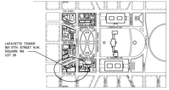
Building name: Lafayette Tower
Location and Site: 801 17th St. NW, Washington D.C.
Building Occupant Name: Louis Dreyfus Properties
Occupancy or Function Types (type of building): Office / Corporate
Size (total square feet): 328,000 SF
Number of stories above grade: 11
Primary project team:
Construction Manager: Clark Construction Group, LLC
Owner: Louis Dreyfus Property Group
Architect: Kevin Roche John Dinkeloo & Associates, LCC
Structural Engineer: Tadjer-Cohen-Edelson & Associates, Inc.
MEP Engineer: Tolk, Inc.
Civil Engineer: Edwards & Kelcey
Dates of construction: August 2006– December 2009
Building Cost: $47 million
Project delivery method: GMP
Architecture
Architecture
Lafayette Tower is an 11 story core & shell office building located in downtown Washington DC. Its LEED Gold design will comprise 327,688 square feet of mixed use space with the ground floor dedicated to retail. The combination of column-free perimeter and floor to floor glass curtain wall skin will offer spectacular views of the city. Lastly, the penthouse level will have a green roof terrace and there will be three levels of underground parking available for the tenants use.
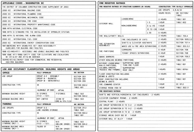
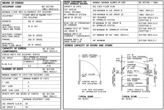
Major National Model Codes
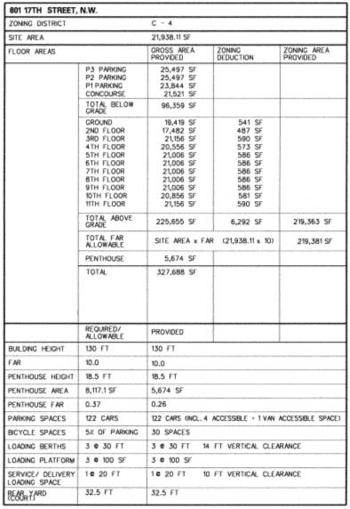
Zoning
Historical Requirements
The site used to house the FDIC headquarters which was demolished to make room for the new building.The site is located approximately 3 blocks and on the main route to and from the White House.
Building Systems
Demolition
Before September 2006, the site was home to the Federal Deposit Insurance Corporation or the FDIC who has now moved to 550 17th Street NW. Demolition began September 11th 2006. Clark started by completely gutting the interior of the building, removing anything that wasn’t linked to the structural system. That was completed November 14th of the same year and which time they started the structural demolition.
To take down the structural system, they started by using skid steer with a hydraulic demolition hammer attachment to deconstruct the upper floors. The process they followed was to crush up the decks of the floor that they had the skid steer on then move down to the next floor to knock out the columns. This repeated until they could get in reach of the excavators with hydraulic shears.
Once in reach of the excavators, the demolition process sped up significantly. The sequencing went from basically going floor by floor to taking out sections of the building from top to bottom.
Cast-in-Place Concrete
The structure of the building is made up entirely of cast-in-place concrete.
All of the slabs below grade are 8 ½” or 10 ½” thick where as all of the slabs above grade are 10” or 12” thick and also utilize post tensioning to allow for larger spans between columns and provide support for the cantilevered slabs that extend out past the exterior row of columns. The concrete for the slabs was put in place by a pump truck.
The columns were put in place by using vertical formwork and the crane and bucket method. The sizes of columns range from 24x40 to 24x12. Slanted columns were used 13 cases all below grade on either the P1 or Concourse level. Slanted columns allow you to stray from typical bays throughout your entire build but still transfer the load down from above.
Mechanical System
Although there are small mechanical rooms on each of the above ground floors (each floor has its own AHU because each floor will host a different tenant), the main mechanical room is located on the P2 Parking level. The key system components that it houses are (2) water chilling units, (2) condenser water pumps, (1) chilled water pump, (1) heat exchanger. The only other major pieces of equipment in the building are (2) cooling towers that are located on the roof.
For fire suppression, both wet and dry systems are used. Wet is the primary system but a dry system is used in the spaces that aren’t heated such as the parking levels and parts of the concourse level. Quick response heads are used throughout the building.
Electrical System
Lafayette Tower’s electrical service is supplied by Pepco, a regulated electric utility that provides transmission and distribution services. The main feed is brought into the building and stepped down to 3Φ, 3000A, 265/460V before it goes into either of the 2 main switchboards that provide power for the rest of the building.
An emergency generator is located just north of the loading dock on the first floor. It is a 500KW/625KVA diesel generator with a 250 gallon tank. This generator would not be able to support the building running at full capacity for more than a couple of hours without being refueled during the outage.
Masonry
All of the masonry used on this job is non load bearing. It is mainly used in the stair wells and the exterior walls for the first two floors on parts of alley and the alley is the only place where scaffolding was used. It is also used as partitions for parts of the first floor and all the below grade levels.
The brick used in the alley is tied back into the building after every two layers by masonry wall ties. There is also a curtain wall stack joint with continuous masonry cap flashing that ties the bricks into the curtain wall coming down from above.
Curtain Wall
An elaborate curtain wall system is used for almost the entirety of the building. There are many box-ins and outs to make the building appear that it is made of glass Legos. There are two main materials used for construction which are aluminum and glass. The assemble involves two layers of glass with an air gap in-between with a coating on the inside of the outer piece of glass to promote heat transfer and it is held together with the aluminum. The design and assembly is the responsibility of Trainor Glass Company.
The individual piece of curtain wall are manufactured in Trainor’s shop where they are then packaged up and shipped to site ready to be installed as soon as they arrive. This process is called unitized glazing which allows for the glass to be set faster and cheaper. To get the glass into place, Trainor uses a crane to lift the panels to the floor above where the panel will actually be set then they use a mobile floor crane to lower them into place and attach them to the rest of the system.
The major benefits of this system is that it not only lowers energy costs and looks cool architecturally but it also does not impose loads on the structural system of the building and it is flexible so that it can move with the wind or expansion from heat.